Bevel Gear Generator
Generate a straight bevel gear pair as printable STLs and turn a rotation through 90 degrees. Set the module, the wheel and pinion tooth counts and the pressure angle; the generator computes the paired cone geometry for right-angle shafts and exports wheel and pinion as separate STL files in one ZIP. Check contact and mounting before use.
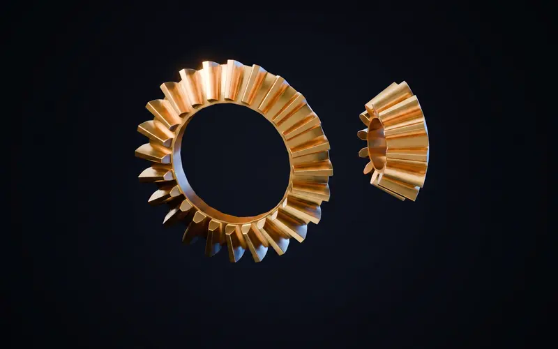
What a bevel gear generator does
A straight bevel pair uses conical pitch surfaces for intersecting shafts. This generator models a 90 degree pair from both tooth counts. In that case each pitch-cone angle is arctan(its teeth / mating teeth), giving 45 degrees for equal counts. Both gears must be specified together: the ZIP export contains separate wheel and pinion STL files. This paired geometric model is not a native CAD feature or a tested physical gearbox.
Mounting distance: the parameter that decides everything
Position both gears so their pitch-cone apexes meet at the shaft-axis intersection. Axial position affects contact and backlash. Provide repeatable locating surfaces and an adjustment method. Allowable mounting error depends on geometry and application, not a universal one-millimeter threshold.
For 20 and 10 teeth, pitch-cone angles are approximately 63.4 and 26.6 degrees. If the 10-tooth pinion drives the 20-tooth wheel, wheel speed is halved. Reversing input and output increases speed instead. A tooth-count ratio does not establish transmitted torque capacity.
Check the pair by hand and inspect tooth contact before applying drive power. Adjust mounting deliberately and recheck backlash. Do not use wear to correct an incorrectly positioned pair. For parallel shafts, a spur pair has a simpler reference center-distance calculation.
How well do bevel gears 3D print?
Inspect the chosen orientation, overhangs and supports in the slicer. Tooth size, cone angle, face width, material and settings affect the result. The gear printing guide explains documenting a trial; one module or filament does not guarantee a durable bevel pair.
Frequently asked questions
Why does the generator always export a pair?
Both tooth counts determine the paired cone angles. The ZIP contains wheel and pinion STL files from that configuration. Replacement geometry must match the complete specification, not just a tooth count.
Can the shaft angle be something other than 90 degrees?
The current bevel mode models 90 degree shaft intersections. Other shaft angles need a different geometric calculation and are not offered by this mode.
How do I get the mounting distance right in a printed assembly?
Use defined locating surfaces or spacers, verify the common cone apex and check tooth contact and backlash with the drive stopped. The correct position depends on the actual pair.
What ratio can a printed bevel pair handle?
Check the ratio together with interference, tooth dimensions, contact and intended load. This page has no tested universal 3:1 operating limit or load rating.
Do bevel gears create axial thrust?
Yes, both gears push away from the mesh along their own axes. Printed assemblies should back each gear with a face that can take that thrust, such as a washer against a housing wall.