Gear Module Explained
Published 2026-08-26 · updated 2026-09-05
Editorial: GenerateSTL
Gear module is pitch diameter divided by tooth count: m = d / z, in millimeters. It sets tooth size, while tooth count sets how many teeth fit around the gear. This guide takes you from that definition to a correctly sized spur-gear pair, including diametral pitch for US drawings and the checks a replacement gear needs before printing.
Start with the pitch circle, not the outside edge
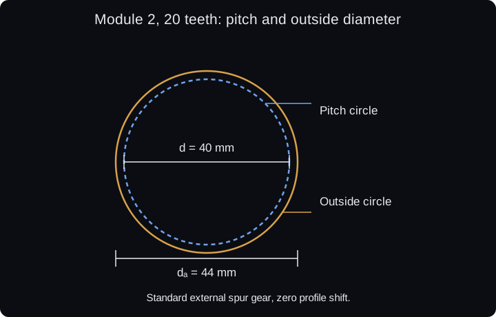
The pitch circle is the reference circle used to describe the gear mesh. It lies below the tooth tips on an external spur gear. A 20-tooth gear at module 2 has a 40 mm pitch diameter; its outside diameter is larger. Confusing those two diameters produces the wrong module even when the caliper measurement is accurate.
KHK’s gear dimension reference distinguishes standard spur gears from profile-shifted and helical gears. The simple formulas below describe standard, full-depth external spur gears with no profile shift. Matching gears need a compatible tooth system, the same module and the same pressure angle.
The standard spur-gear formulas
Use millimeters for every diameter and center distance. Module 2 with 20 teeth gives the values below. Tooth height and root diameter describe the standard reference proportions; a generated root fillet or manufacturing process can change the detailed root shape.
Conversely, a 40 mm pitch diameter divided by 20 teeth gives m = 40 / 20 = 2 mm. This uses the pitch diameter, not the 44 mm outside diameter.
| Quantity | Formula | m = 2, z = 20 |
|---|---|---|
| Pitch diameter d | m × z | 40 mm |
| Outside diameter da | m × (z + 2) | 44 mm |
| Reference root diameter df | m × (z − 2.5) | 35 mm |
| Circular pitch p | π × m | 6.283 mm |
| Center distance to a 40-tooth wheel | m × (20 + 40) / 2 | 60 mm |
Module and diametral pitch for US drawings
Diametral pitch, DP, counts teeth per inch of pitch diameter. Its unit is inverse inches. Module measures pitch diameter in millimeters per tooth, so m = 25.4 / DP and DP = 25.4 / m. Larger module means larger teeth; larger DP means smaller teeth. Circular pitch is another quantity: the distance from one tooth to the next along the pitch circle.
For a 16 DP gear, m = 25.4 / 16 = 1.5875 mm. A 32-tooth wheel then has a 50.8 mm pitch diameter, exactly 2 inches. Keep the converted value when matching an existing gear. Rounding it to module 1.5 creates a different tooth spacing.
Use the gear module and DP calculator for conversions. The calculation does not identify the pressure angle or prove that an old gear uses a standard tooth form.
For a 12 DP drawing, m = 25.4 / 12 = 2.11666… mm. Preserve the available precision through the calculation; round only the displayed result.
| Diametral pitch | Module | Pitch diameter, 32 teeth |
|---|---|---|
| 32 DP | 0.79375 mm | 25.4 mm |
| 24 DP | 1.05833… mm | 33.8667 mm |
| 16 DP | 1.5875 mm | 50.8 mm |
| 12 DP | 2.11666… mm | 67.7333 mm |
A worked pair: 20 teeth driving 40 teeth
Choose module 2, a shared 20° pressure angle and zero profile shift. The pitch diameters are 40 and 80 mm. Their radii add to a nominal 60 mm center distance. With the 20-tooth gear as input, the 40-tooth gear turns at half the input speed in the opposite direction. Changing module changes the size, while this tooth-count ratio stays 2:1.
Open the spur gear generator for each wheel. Check the housing and shaft positions with the gear center distance calculator. Face width, shaft fit and running clearance still need separate decisions; the nominal center distance is not a printer calibration.
Estimate the module of a replacement gear
Count every tooth, then measure across undamaged tips at several angles. For an unshifted standard external spur gear, m ≈ da / (z + 2). A 22-tooth gear measuring 48 mm outside gives 48 / 24 = 2 mm. Treat this as an identification candidate, then check the mating gear, center distance and pressure angle.
Wear, tip chamfers, profile shift and nonstandard tooth depth can all disturb the estimate. A helical gear also needs its helix angle and module system identified. An unusual result alone does not prove an imperial gear: measurement error and modified geometry can produce the same symptom.
Choose a printable size without changing the design blindly
A coarser module makes larger tooth features at the same tooth count, but there is no universal minimum printable module. Nozzle, layer height, extrusion width, material and load matter. Prusa’s design guidance explains why feature size and orientation must be checked in the slicer.
Inspect a sliced tooth and root before printing a pair. If the slicer omits a thin feature, change the design or process; more infill cannot recreate a missing perimeter. For an existing drivetrain, preserve module and pressure angle and tune the manufacturing process instead of enlarging one replacement gear.
The 3D printed gears guide covers a repeatable fit test. For a sun, ring and planets, continue to planetary gears explained: sharing a module is only the first assembly condition.
Where these formulas stop
For helical gears, distinguish normal module from transverse module. Pitch diameter uses transverse module; normal module converts through the helix angle. For bevel gears, the reference cone and the specified end of the tooth matter. Do not apply the outside-diameter shortcut to either type without checking those definitions.
Profile shift changes tooth thickness and reference tip/root dimensions; mating shifted gears can require a different working center distance. It is not a generic backlash slider. Use the relevant sections in KHK’s dimension calculations when leaving the standard spur-gear case.
Frequently asked questions
Is module the same as pitch?
No. Module is d / z in millimeters. Circular pitch is π × module. Diametral pitch counts teeth per inch of pitch diameter and converts as DP = 25.4 / m.
Can I calculate module from the outside diameter?
Approximately, for a standard unshifted external spur gear: m = da / (z + 2). Worn teeth, profile shift, helical geometry and nonstandard tooth depth can invalidate that shortcut.
Does a larger module guarantee a stronger printed gear?
No. It enlarges the tooth geometry at the same tooth count. Material, face width, print orientation, root shape, speed and load still determine whether the part works.
Do matching module values guarantee a correct mesh?
No. Pressure angle and tooth system must also match. Shaft position, profile shift, interference and manufacturing clearance need checks of their own.