3D Printed Threads: A Reproducible M8 Test
Published 2026-08-26 · updated 2026-09-25
Editorial: GenerateSTL
Printed threads rarely fail because the diameter is wrong. They fail because the two parts disagree about profile, pitch, starts or hand, or because a clearance was copied from a different printer. This guide loads one complete, versioned M8 recipe, explains what each value does to the modeled geometry, and walks a short rod and nut test you can measure and record.
Why printed threads fail to fit
A printed thread is a pair of surfaces, and the pair only works when both sides describe the same thread. Diameter is the most visible value, but it is not the deciding one. A nut cut for the M8 coarse pitch will not run on a rod printed at the M8 fine pitch, even though both carry the same M8 label. The profile, the number of starts and the hand of the helix have to agree as well. The thread generator lists the profiles the workspace builds, and the nut and bolt generator covers the matching parts.
Pitch is the axial distance from one thread groove to the next (Roton's thread pitch reference). Lead is the distance a matching nut travels in one full turn. For an integer number of starts, lead is pitch multiplied by the number of starts, which is why a multiple start thread converts one revolution into more travel (Roton's Hi-Lead description). One start at the recipe's 1.25 mm pitch gives a theoretical lead of 1.25 mm per turn.
When the thread form matches and the parts still will not fit, the remaining difference comes from the process rather than from the specification. A printer does not reproduce the model exactly: the first layer is squished against the bed and usually ends up wider than drawn (Prusa's elephant foot article), and a wall or an overhang lands near the modeled surface instead of on it (Prusa's modeling guide). The same guide states that there is no single universal tolerance value, because the result depends on the size of the model, the orientation, the geometry that has to interlock, the calibration, the settings and the material. That is why this page fixes the thread form first and calibrates the fit second.
Load the complete M8 recipe
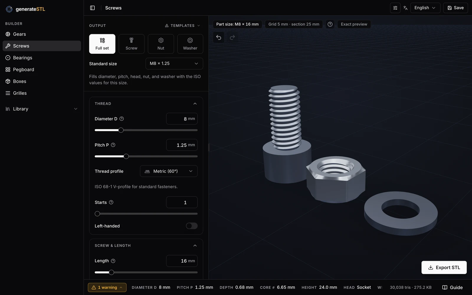
Open the complete M8 recipe in the screw workspace. The link carries the recipe id and the language as a parameter variant of the same tool page. A recipe replaces the parameter set the workspace would otherwise restore from your browser, so what appears after the link loads is the model this guide describes rather than a mixture of old settings.
Every value below is an input to the generator, taken from the published recipe and checked by the repository's own recipe test. The table is not a printing recommendation and not a print result: it is the exact model this test starts from, so that two people who load the same link are looking at the same geometry.
| Setting | Recipe value | What it controls |
|---|---|---|
| Exported parts | Full set: rod, nut and washer | Which parts the workspace exports from this parameter set |
| Rod diameter D | 8 mm | Nominal outer thread diameter |
| Pitch P | 1.25 mm | M8 coarse pitch, the axial distance from crest to crest |
| Thread profile | Triangular | Symmetric 60 degree cross-section of the thread |
| Starts | 1 | A single helix, so the lead equals the pitch |
| Handedness | Right-handed | Normal helix direction, tightening clockwise |
| Rod length | 16 mm | Threaded length of the exported rod |
| Blunt start | Both ends | Thread fades in at both ends instead of stopping abruptly |
| Plain shank | 0 mm | No unthreaded segment at the start of the rod |
| Rod end bevel | None | No 45 degree chamfer on the rod ends |
| Rod undersize | 0 mm | No reduction of the modeled outer diameter |
| Head | Socket | Socket head cap form on the rod |
| Head diameter | 13 mm | Width of the socket head |
| Head height | 8 mm | Height of the socket head |
| Drive | Hex | Hexagon socket in the head |
| Drive size | 6 mm across flats | Hex key size the pocket accepts |
| Drive depth | 4 mm | Depth of the hex pocket |
| Nut shape | Hex | Outer form of the nut |
| Nut width across flats | 13 mm | Wrench size of the nut |
| Nut thickness | 6.8 mm | Height of the nut |
| Nut bevel | Automatic | Face and thread-entry chamfers generated from the model rules |
| Nut edge chamfer | 0.2 | Edge chamfer relative to the nut thickness |
| Nut clearance | 0.12 mm | Radial offset of the nut thread profile, explained below |
| Nut flush bottom | No | Bottom face keeps the generated bevel |
| Washer inner diameter | 8.4 mm | Clearance bore of the washer |
| Washer outer diameter | 16 mm | Outside diameter of the washer |
| Washer thickness | 1.6 mm | Height of the washer |
| Washer chamfer | 0 | No chamfer on the washer edges |
| Resolution | 3 (Fine) | Curve tessellation of the exported mesh |
Separate rod undersize and nut clearance
Rod undersize and nut clearance both change the fit, but they act on opposite surfaces. Undersize shrinks the modeled outer diameter of the rod, so it moves the crests inward. The recipe keeps it at 0 mm, which leaves the rod at the diameter the metric table gives M8. Nut clearance offsets the internal thread of the nut outward instead. In the current geometry the nut profile receives a radial offset of twice the setting, and the app's own hint states that the bore grows by four times the value across the diameter.
The recipe's nut clearance is 0.12 mm because that is the default of the builder, not because 0.12 mm has been established as a good printing clearance. A clearance that works on one printer, nozzle, material and orientation can be wrong on the next, which is exactly the point Prusa's modeling guide makes when it says there is no universal tolerance value. Treat 0.12 mm as the value this test starts from. If your printer needs a different figure, that figure is something you measure, and this page cannot hand it to you.
Do not subtract an allowance from the nominal diameter and then add the same allowance again as nut clearance. The two controls move different surfaces, and using both at once leaves you unable to say which one produced the result. For a printed nut on a purchased metal screw, keep the nominal thread specification and calibrate the nut alone. For a printed pair, change one control per test print.
Export and inspect a short test pair
Load the recipe again and export the rod, the nut and the washer, then inspect the STL files in your slicer before printing anything. Check that the thread runs the length you expect, that the flanks survive the preview at your layer height, and that the nut entry is not filled with support. The preview shows the modeled geometry, so a clean preview is a statement about the mesh and nothing more.
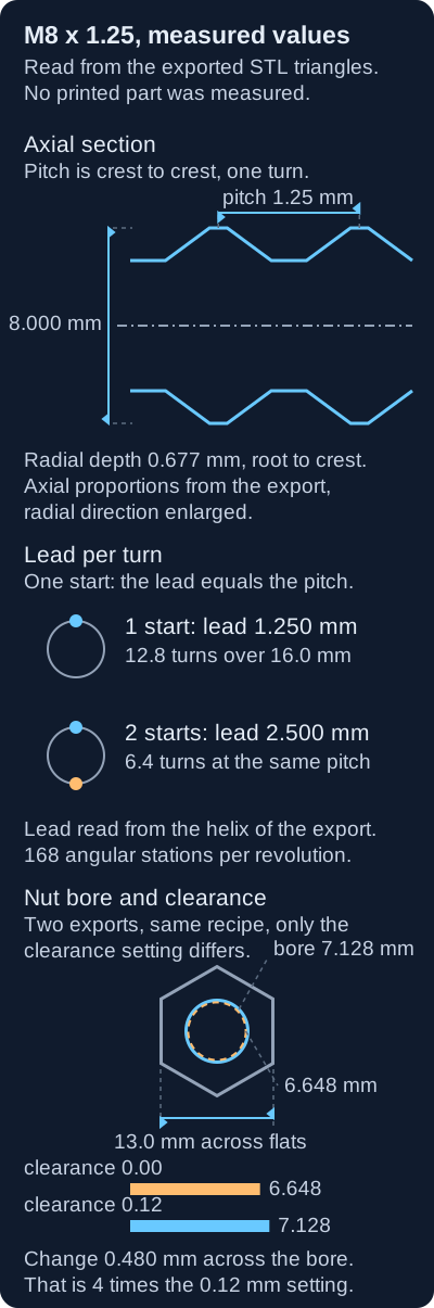
Measured on the exported triangles, the rod is 8.000 mm across the crests, so the crests reach the nominal diameter instead of sitting inside it. The crests repeat every 1.25 mm, and one full turn of the single start helix advances 1.2499989 mm, which is the 1.25 mm pitch within the 0.00008 mm uncertainty the measurement reports. A second export with two starts advances 2.4999996 mm per turn, so the lead doubles while the crest spacing stays at 1.25 mm. The same rod file spans 24.0 mm in total, an 8 mm socket head plus 16.0 mm of thread.
The nut body is 13.0 mm across the flats, which is the wrench size, and 6.8 mm thick. Raising nut clearance from 0.00 mm to 0.12 mm widens its narrowest bore diameter from 6.648 mm to 7.128 mm. That is a change of 0.480 mm across the diameter, exactly four times the setting, which confirms the relation the interface describes and shows how quickly the number you type grows once it acts on a diameter.
Every figure above was read from the exported STL files rather than from a printed part, and the full measurement record with its exact commands and input hashes is kept with this guide's verification files. The same record reports closed surfaces and no degenerate triangles for the rod, the nut and the washer, which is a statement about the files and not about any print.
Two of these numbers decide whether a print is worth starting. If the major diameter is not at nominal size, or the lead does not match the pitch on a single start rod, the two parts were not generated with the same settings, and no clearance value repairs a form mismatch.
Record your print process and fit
A fit result without the process behind it cannot be compared with anything, not even with your own earlier print. Record the fields below before the print, then fill in the values after it. The value column ships empty on purpose: this page has not printed your part, and a result copied from another workshop would say nothing about your printer.
| Record | Your value |
|---|---|
| Printer, nozzle diameter and layer height | |
| Filament type and whether it was dried | |
| Orientation of the rod on the build plate | |
| Orientation of the nut on the build plate | |
| Slicer compensation enabled, with its value | |
| Measured rod major diameter, in mm | |
| Measured crest-to-crest pitch, in mm | |
| Travel per full turn, in mm | |
| Nut width across flats and thickness, in mm | |
| Where the nut starts to bind, in turns | |
| Whether the pair runs free by hand after cooling |
Change one variable at a time
Work through the causes in order, because a later check cannot rescue an earlier mistake. First confirm that profile, pitch, starts and hand are identical on both parts. Second, check whether the nut starts at all: when it refuses to start, the entry geometry, an expanded first layer or a damaged crest is a likelier cause than overall tightness. Third, when it starts and then binds progressively, look at lead, accumulated print error and alignment before you touch a clearance. Fourth, a tight spot at one angular position points to a seam, a deposit or a damaged thread rather than to a size error. Fifth, when only the first layer catches, remember that the first layer is wider than the model, which is the effect elephant foot compensation addresses (Prusa's elephant foot article).
Once the thread form and the process are excluded, change exactly one value between two prints. Move the rod undersize or the nut clearance, not both, and measure the same two or three values after each print. A test that moves two controls at once cannot tell you which one closed the gap, and the next print repeats the same guess with a different label.
This is the isolate-one-variable method that the 3D printed gears guide applies to mesh and backlash, and it holds here for the same reason: a printed pair has more than one source of error, and only a recorded change separates them. Swap the printed pair for a purchased fastener when the joint has to carry a defined load or survive repeated use, because nothing on this page measures strength.
Frequently asked questions
Does M8 specify the printed fit?
No. M8 specifies the nominal thread form: an 8 mm outer diameter with a 1.25 mm coarse pitch or a 1.0 mm fine pitch. It says nothing about how much clearance your printer needs, and it is neither a tolerance class nor a strength certificate. The printed fit comes from the model inputs you choose and from the process you record around them.
What is the difference between pitch and lead?
Pitch is the axial distance from one thread crest to the next. Lead is the distance a nut travels in one full turn. On a single start thread the two are equal, so the recipe at 1.25 mm pitch advances 1.25 mm per turn. With two starts the lead doubles while the crest spacing stays at the pitch value.
Should I change rod undersize and nut clearance together?
No. They move opposite surfaces, so changing both in one print leaves the result unattributed. Change one, print, measure, then decide. Keep the rod undersize at 0 mm while you calibrate the nut, or hold the nut at the recipe value while you test the rod.
Does the generator support fine and multiple-start threads?
Yes. It offers metric coarse and selected fine pitches as separate values, one to six starts, and left-handed threads. Both mating parts have to share profile, pitch, starts and handedness, and the recipe in this guide uses the M8 coarse pitch with one right-handed start.
Can I reuse the 0.12 mm nut clearance for another material?
Not as a recommendation. That value is the builder's default for the model, and a required clearance changes with model size, orientation, interlocking geometry, calibration, settings and material. Start from the recipe, print one pair, measure it, and let your own record decide the next value.