3D Printed Gears: Materials, Fit and a Test Log
Published 2026-08-26 · updated 2026-09-08
Editorial: GenerateSTL
A usable 3D printed gear needs a compatible tooth profile, a dimensionally accurate print and a material suited to its duty. Start with a small pair you can inspect before building the full mechanism. Use the 20/40-tooth example, blank CSV log and printable worksheet below to compare your own trials. The method helps you document fit; it does not establish a universal load rating or service life.
Define the job before choosing a filament
Write down the tooth counts, module, pressure angle, speed, expected torque, operating temperature and required running time. A hand-turned demonstration and a motor running all day are different jobs. Specify the shaft and housing too: gears cannot correct moving or misaligned axes.
The distinction between material and application is visible in igus’s printed-gear guidance, which uses application inputs and material-specific wear data. Its results for its own polymers are not a load rating for an arbitrary PLA or PETG print. Use the module guide to establish the dimensions first.
Material choice: compare requirements, not a winner
Prusa’s filament guide separates heat resistance, toughness, print difficulty and other properties. Choose a specific grade using its supplier data and a profile suitable for your printer. Polymer names alone do not establish gear wear, friction or lifespan.
PLA can be useful for checking shape and motion with a familiar printing process. PETG is another candidate for prototypes, but its toughness does not guarantee low wear. Nylon grades may be useful for moving parts; check drying, shrinkage and conditioning requirements. Filled, wear-optimized and unfilled polymers require their own data.
| Candidate | Question before use | What to verify on the part |
|---|---|---|
| PLA | Is the operating temperature suitable for this grade? | Fit and deformation under the intended duty |
| PETG | Do the flanks print cleanly with this profile? | Stringing, clearance and wear during a controlled test |
| PA / nylon | Can the filament be dried and printed as specified? | Dimensions after conditioning and operation |
| Specialist gear polymer | Is application-specific test data available? | Whether its tested conditions match your mechanism |
Slice the teeth, root and bore before printing
Use a stable printer/material profile, then inspect the toolpaths. Prusa’s design guidance explains why orientation and feature dimensions affect the print. For a spur gear, placing one flat face on the bed is a useful candidate orientation. Check other orientations where the hub or loading makes that necessary.
Look for continuous paths through each tooth root and sufficient solid material around the bore. Wall count and infill work together; neither one has a universal strength threshold. A fine layer height can improve the representation of sloped features, but it does not by itself establish accuracy or strength.
Keep supports out of working flanks where removal would damage them. Helical, herringbone and bevel parts need their own overhang and contact checks. A shape that can be generated is not automatically support-free on every machine.
Separate shaft fit, tooth clearance and center distance
Shaft fit controls the connection between a bore and its shaft. Tooth clearance controls the mesh. Nominal center distance positions the two gear axes. Changing one to hide a fault in another can make the mechanism unreliable.
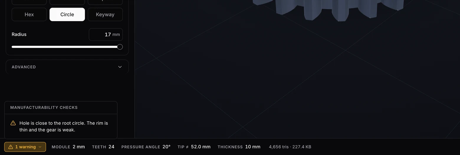
The circular-hole control in the gear generator uses a radius. For a chosen model bore of 8.2 mm diameter, enter 4.1 mm radius. The export uses that radius directly; it does not silently add 0.2 mm. This arithmetic example is not a recommended allowance. Determine the desired diameter with a small coupon and your actual shaft.
Set the nominal shaft spacing with the center distance calculator. Measure the printed gears and inspect the mesh before adjusting it. Profile shift changes the tooth geometry and can affect the required working center distance; do not treat it as a generic backlash control.
A repeatable first-pair test
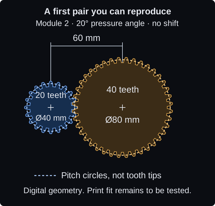
Generate a 20-tooth pinion and 40-tooth wheel with module 2, 20° pressure angle and zero profile shift using the spur gear generator. Their nominal center distance is 60 mm. Choose bores and face width for your fixture. This is a test procedure you can carry out, not a report of a physical test performed for this article.
Record the following before changing any setting. Print both parts, inspect and measure them, mount them without power and turn the pair through complete revolutions. Identify any repeatable tight spot. A freely turning pair passes that hand check only. Evaluate any powered test separately using a fixture, containment and stopping criteria appropriate to the application.
The dashed circles in the drawing are pitch circles. Their radii are 20 and 40 mm, so the theoretical axis spacing is 20 + 40 = 60 mm. The visible tooth tips extend farther. This standard, unshifted spur-pair calculation follows KHK’s gear dimension reference; it does not add a printer-specific allowance.
| Record | Purpose |
|---|---|
| Generator parameters and exported files | Reproduce the geometry |
| Printer, nozzle, filament grade and condition | Identify the manufacturing process |
| Layer height, walls, infill, seam and orientation | Reproduce the slicer result |
| Bore measurements and shaft spacing | Separate fit errors from tooth errors |
| Fixture, binding position, backlash and visible wear | Compare one controlled change at a time |
Use the log to compare one change at a time
The CSV contains a header and one empty row. Open it in Excel, Google Sheets or another spreadsheet, then use one row per trial. If the columns do not split automatically, import it as UTF-8 with a comma delimiter. Keep the trial ID with the STL files and printed parts. The two-page worksheet has the same fields for handwritten notes. Neither file contains example results.
First record the geometry, printing profile and fixture. After cooling, measure the bores, shafts and actual axis spacing with the same method. For a comparison, copy the baseline to a new trial ID, identify one changed variable and record its old and new values. Leave measurements you did not take blank. Prusa’s design and tolerance guidance explains why a fit allowance depends on geometry, orientation, process and material.
Describe what was held still and where you checked movement. Shaft movement or a flexible fixture can contribute to the play you observe, so do not label all movement as tooth backlash. Repeat the check at the same location and record any tight spot by its position in the rotation.
Application-test fields are optional. Use them only for a test you actually perform: record speed, time or cycles, temperature and the measurement location. If force is measured through a lever, record the perpendicular lever radius too. Force in newtons and torque in newton-meters are different quantities. Note the reason for stopping and visible damage. An empty torque field is more useful than an assumed strength rating.
Diagnose the failure instead of adding a fixed allowance
Binding throughout a revolution suggests checking tooth compatibility, shaft spacing and over-extrusion. One tight spot suggests runout, a seam or a damaged tooth. A poor shaft fit belongs in the bore calibration. Root cracking calls for a review of load, root geometry, material and print structure; appearance alone does not identify one guaranteed cause.
A widened first layer can also interfere with the mesh. Prusa’s elephant-foot explanation describes that effect and its compensation. Correct a measured problem rather than applying a fixed offset to every surface.
If lubrication is appropriate, check compatibility with the exact polymer and operating environment. Do not assume a lubricant halves wear or makes an under-designed gear safe. Use the planetary guide before combining rings and planets: those assemblies introduce additional interference checks.
Method, sources and corrections
This guide combines the linked manufacturer references with the generator’s own parameter definitions. The 20/40 example uses calculated dimensions; its tooth outlines come from the tool’s involute geometry. The worksheet is a proposed recording method with no measured results. No physical gear test, material ranking or service-life measurement was performed for this guide.
The editorial responsibility is GenerateSTL. To report a correction, use the public project issue tracker and identify the section, parameter or calculation involved. The public geometry engine lets you inspect how exported parts are constructed.
Frequently asked questions
What is the best filament for gears?
There is no universal winner. Match a specific grade to temperature, speed, load, wear and your printing process. Supplier data and a representative test are more useful than ranking all nylon, PETG and PLA together.
How much infill do printed gears need?
Inspect the sliced teeth, root, hub and bore together. Walls and infill affect different regions. This guide does not assign a strength threshold to one infill percentage.
Does the generator add 0.2 mm to a gear bore?
No. The circular bore uses the entered radius directly. If your chosen model diameter is 8.2 mm, enter 4.1 mm radius. Choose any allowance from a fit test.
Can I fix a binding mesh with profile shift?
Do not use profile shift as a generic clearance adjustment. It changes the tooth geometry and can change the working center distance. Check module, pressure angle, axis position and measured print errors first.