Understand the geometry. Check the numbers.
Spur gear center distance calculator
Calculate the reference distance between the shafts of two standard external spur gears. Enter one shared module and both tooth counts. The result applies to unshifted spur gears with compatible tooth geometry, not to internal, helical or bevel gear pairs.
Your inputs
Results update immediately. Decimal point or comma accepted.
0.01 ≤ m ≤ 100
Whole number, 6 to 1,000.
Whole number, 6 to 1,000.
Calculated result
- Reference center distance
- 60 mm
- Center distance in inches
- 2.362205 in
- Pitch diameters
- 40 / 80 mm
- Input / output speed magnitude
- 2 : 1
a = 2 × (20 + 40) / 2 = 60 mm
Gear 1 drives gear 2. Rotation is opposite. No profile shift or printing-clearance allowance is included.
Formula and assumptions
The reference pitch diameters are d₁ = m × z₁ and d₂ = m × z₂. Their sum gives a = (d₁ + d₂) / 2 = m × (z₁ + z₂) / 2. The calculator reports the distance between shaft centers, not between the outside edges of the gears.
Use the same module and pressure angle for both gears. The reference center distance assumes zero profile shift and standard external spur geometry. A nonzero profile-shift sum requires an operating-pressure-angle calculation; adding an arbitrary offset is not an equivalent calculation.
Technical reference: KHK: Calculation of Gear Dimensions, table 4.1.
Worked pair: 20 teeth driving 40 teeth
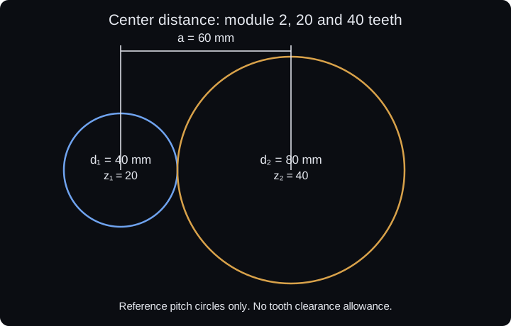
For module 2 mm, z₁ = 20 and z₂ = 40, the pitch diameters are 40 mm and 80 mm. The shaft centers are 2 × (20 + 40) / 2 = 60 mm apart, approximately 2.362205 inches.
With gear 1 as input and gear 2 as output, the speed-reduction magnitude is z₂ / z₁ = 2. Gear 2 turns at half the speed and in the opposite direction. This ratio alone does not predict available output torque or efficiency.
Why a printed pair can still bind
The reference center distance is a geometric starting point. Tooth thickness, backlash, runout, shaft alignment and printing accuracy determine whether the assembled parts move freely. A number from this calculator does not include a printing-clearance allowance.
Check the tooth mesh in CAD and print a short pair before building a complete housing. Inspect first-layer expansion and the bore fit separately. Changing the shaft spacing also changes the operating mesh, so keep any adjustment explicit in the design.
Generate the two gears separately
Each button opens one external spur gear with its calculated module and tooth count. The links explicitly set 20° pressure angle, zero profile shift and 10 mm height. The generator produces individual parts; this transfer does not build a paired assembly or position shafts.
Review both models before export. The calculator accepts module 0.01 to 100 mm and 6 to 1,000 teeth per gear, while direct transfer supports module 0.3 to 75 mm and 6 to 150 teeth. A valid center distance is not a check for undercut, contact ratio or strength.
Common questions
Can I use the formula for an internal gear?
No. An unshifted internal pair uses half the difference of the pitch diameters. That is a separate geometry and is not calculated in this tool.
Can I enter an imperial diametral pitch?
Convert DP to metric module with the linked module calculator first. This calculator takes module in millimeters and shows center distance in both millimeters and inches.