Print-in-Place Bearings: Clearance and Fit Checks
Published 2026-08-26 · updated 2026-09-05
Editorial: GenerateSTL
The bearing generator makes a print-in-place plain bearing: two shaped rings slide against one another, or a third sliding ring sits between them. It does not generate balls or rollers. This guide explains the geometry, radial clearance and a repeatable first-print check so you can assess a custom bearing before using it in a mechanism.
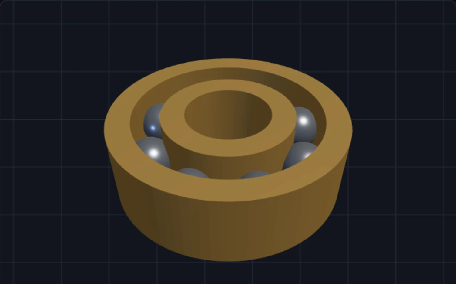
What this printed bearing contains
Open the bearing generator and choose two or three rings. The shaped cross-sections retain the rings axially while leaving a gap for relative rotation. In the three-ring option, the middle ring also slides. This is a plain-bearing arrangement, even when its outside dimensions resemble a familiar ball bearing.
A rolling bearing transfers contact through separate rolling elements. Here, the printed surfaces themselves slide. Matching a purchased bearing’s bore, outside diameter and width does not reproduce its load rating, friction, precision or service life. Use this geometry for a prototype you can evaluate, not as an automatically equivalent industrial replacement.
Define the bore, envelope and radial clearance
The current 22/8/7 preset specifies 22 mm outside diameter, 8 mm bore and 7 mm width. These are nominal model dimensions. The bore must fit your shaft; the outside diameter must fit your housing. Neither fit is calibrated by selecting the preset.
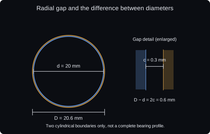
Clearance is the nominal radial gap between neighboring ring profiles. A 0.3 mm radial gap corresponds to a 0.6 mm difference between the two opposing diameters at a cylindrical section. It is not a 0.3 mm allowance to add separately to the shaft bore. Sloped retaining surfaces need inspection too; the radial gap is not a promise of equal clearance in every direction.
| Parameter | Current example | What it controls |
|---|---|---|
| Outside diameter | 22 mm | Outer envelope |
| Bore diameter | 8 mm | Hole through the inner ring |
| Width | 7 mm | Axial envelope |
| Rings | 2 | Two sliding rings |
| Radial clearance | 0.3 mm default | Model gap, to calibrate for the process |
Inspect the sliced gaps before printing
Keep the bearing axis perpendicular to the bed as an initial layout, then inspect every layer through the retained surfaces. Prusa’s design guidance explains how orientation, overhangs and small features affect a print. The generated model still needs to be checked in your slicer.
Look for separate toolpaths on both sides of each gap. Disable or locally exclude supports that would be trapped inside it. If the slicer cannot preserve the gap or the overhang needs inaccessible support, revise the geometry or process before printing. Check seams and travel paths for material that could bridge the rings.
Choose a filament with a profile you can reproduce and consult its material-specific requirements. A familiar material helps isolate geometry problems. This guide does not rank an untested PETG, PLA or nylon bearing by friction or wear.
Run a controlled clearance comparison
Start with the default model and record printer, nozzle, filament grade, layer height, extrusion width, temperatures, seam location and support settings. Export and slice the model. This is a proposed test method; no physical test result is being claimed for the article.
If the default does not give suitable motion, compare small clearance changes while keeping every other parameter fixed. For example, 0.25, 0.30 and 0.35 mm form a test series around the default. Those are candidate model gaps, not material-specific recommendations. Label each print so the result can be traced to its configuration.
After cooling, inspect the gaps and first layer. Try gentle hand rotation only. Do not force a welded assembly until it fractures. Record whether it rotates, where it binds, and how much unwanted movement it has. A setting that works on this size still needs checking when the geometry or printing process changes.
Find the cause of a stuck or loose bearing
A widened first layer can connect otherwise separate surfaces. Prusa’s elephant-foot guide describes the effect and compensation. First determine whether the obstruction is confined to the bed-facing edge or continues through the full height.
| Observed problem | Inspect next | Controlled next step |
|---|---|---|
| Joined at the bottom | First-layer expansion and brim contact | Correct the first layer or measured compensation |
| Joined through several layers | Extrusion, seam deposits and sliced gaps | Correct flow or test a larger model gap |
| Turns unevenly | Local seam, debris or warped ring | Locate and remove the cause before changing all gaps |
| Too much unwanted movement | Model clearance and retaining geometry | Test a smaller gap and recheck freedom of motion |
| Works alone, binds in the housing | Housing squeeze and shaft alignment | Measure the installed fits |
Decide whether the bearing belongs in the final design
Check the assembled mechanism at its intended speed, load, temperature and duration. A hand-turning test establishes only basic movement. It does not establish a safe working load or long-term wear. For a job needing a specified bearing performance, select a purchased bearing with suitable manufacturer data and design the housing around it.
The 3D printed gears guide explains a similar method for separating shaft fit from gear-mesh errors. If your bearing sits in a threaded assembly, also check the printed-thread fit guide; its clearance controls describe different surfaces.
Frequently asked questions
Is this a 3D printed ball bearing?
No. The generator creates retained sliding rings, with an optional sliding middle ring. It does not create balls, rollers or a cage.
Does a 22/8/7 print replace a 608 ball bearing?
The nominal envelope can match, but the operating principle and performance differ. Those dimensions do not provide a rolling-bearing load rating or lifetime.
What does 0.3 mm clearance mean?
It is the nominal radial model gap between neighboring rings. At a cylindrical section, that means 0.6 mm between the opposing diameters. It is separate from the shaft-bore fit.
Should I force the rings free with pliers?
First inspect for fused layers, trapped support or debris. Forcing a welded part can crack the retaining geometry. Correct the observed cause and reprint when necessary.