Guides
Practical engineering for printed parts: how to pick gear parameters, which materials hold, and the print settings that make mechanisms last.
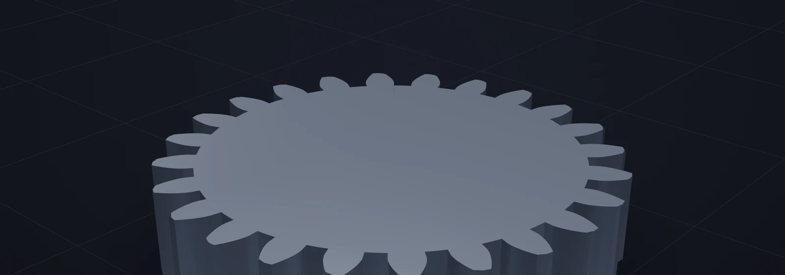
Gear Module Explained
Understand gear module, pitch diameter and diametral pitch.
Open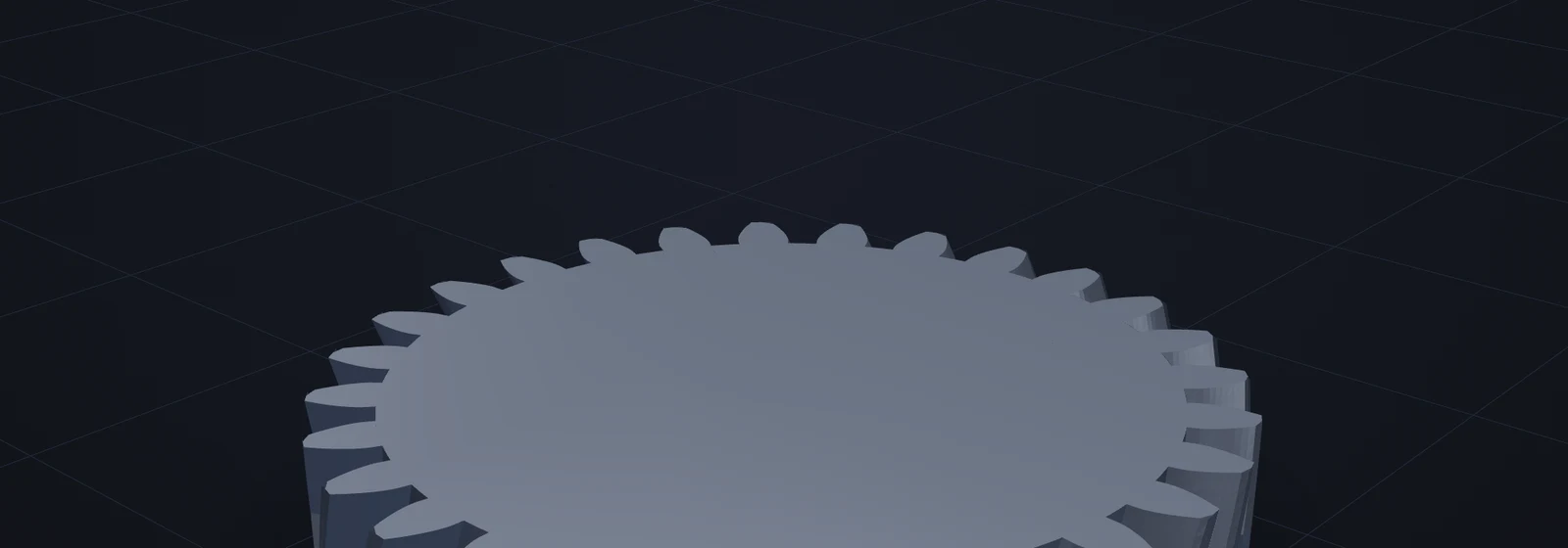
3D Printed Gears: Materials, Fit and a Test Log
Choose materials and settings for 3D printed gears.
Open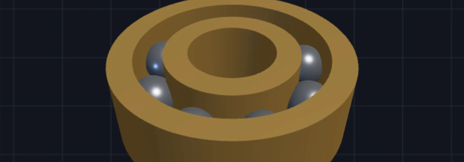
Print-in-Place Bearings: Clearance and Fit Checks
Learn how printed sliding-ring bearings work.
Open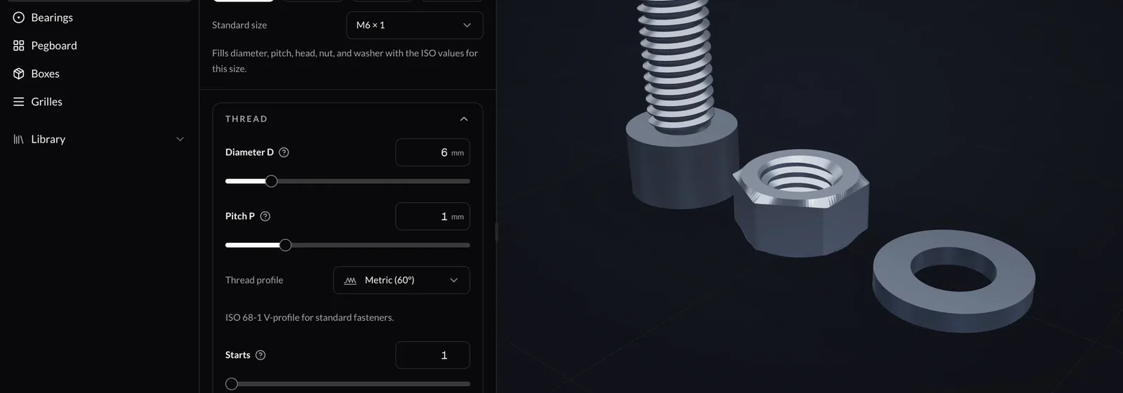
3D Printed Threads: A Reproducible M8 Test
Use a complete M8 thread recipe to inspect pitch, starts and modeled clearance.
Open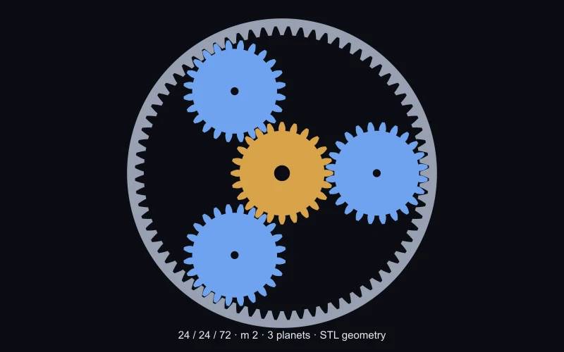
Planetary Gears Explained
Understand planetary sun, planet and ring gears with a 24/24/72 example.
OpenCalculate the dimensions before building the gear
Find module, pitch diameter and center distance, or compare the speeds in a planetary gear set. Each calculator includes its formula, a worked example and the limits of the result.
Gear module and diametral pitch calculator
Calculate gear module from pitch diameter and teeth, convert diametral pitch, and check standard spur-gear dimensions with a worked example.
Spur gear center distance calculator
Calculate center distance for a standard spur-gear pair from module and tooth counts. See the formula, units and limits before setting shaft positions.
Planetary gear ratio calculator
Calculate planetary gear ratios from tooth counts and fixed, input and output members. See rotation direction, assumptions and a worked example.
Useful checks before printing
Separate calculated dimensions from the fit your printer produces.
Pitch circle or tooth tips?
For an unshifted standard external spur gear, pitch diameter is m × z and outside diameter is m × (z + 2). A caliper across the tooth tips does not measure the pitch circle.
Will two spur gears mesh?
Start with compatible module, pressure angle and tooth geometry. The standard center distance is m × (z₁ + z₂) / 2. Profile shift, alignment and print clearance need separate checks.
Which print settings?
Inspect tooth walls and gaps in the slicer. Calibrate with a small pair before printing a complete mechanism. No fixed wall count, infill percentage or material choice certifies load capacity.
What about bore clearance?
The gear builder uses a radius for a circular bore. It does not add a universal fit allowance. Measure a printed calibration hole and adjust the radius for the shaft and fit you need.
Apply it in the generators
Every guide maps to a tool. Set the parameters, watch the mesh update live, download the STL.