3D Print Tolerance Test Generator
Measure your own printer instead of trusting a clearance number from another machine. Generate a cylindrical pin and a plate with six labeled holes, print them together, then record which nominal diametral clearance fits your process. The result describes this print and material, not a universal printer tolerance.
A pin and a hole row instead of a printer benchmark
This test compares one cylindrical pin with a row of holes in a plate, where the holes differ only in diameter. Printing the pin and the whole row in one job keeps material, nozzle, layer height and orientation identical, so the hole diameter is the only variable left between the pairs. That is deliberately not a printer benchmark: it produces no score, only the fit you got with this pin, this plate and this process. A value from another machine does not transfer, because Prusa's design guidance names size, orientation, geometry, calibration, slicer settings and material properties as factors in one fit, and states that no single universal tolerance value exists.
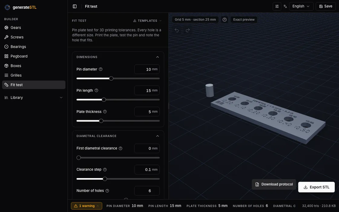
Open the fit test generator to export the pin, the labeled plate and a protocol CSV for the selected dimensions. The blank log and printable sheet below are also available if you want to record a trial by hand. The generated CSV contains nominal values and empty measurement fields; it does not claim that the printed parts have been measured.
Read the gap correctly
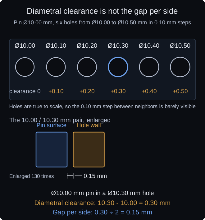
Diametral clearance is the hole diameter minus the pin diameter. At a pin of Ø10.00 mm and a hole of Ø10.30 mm the diametral clearance is 0.30 mm. That difference is distributed around the whole circumference, so the gap between pin and hole wall is 0.15 mm per side, not 0.30 mm per side. Describing it the second way overstates the room the pin really has, and it is the most common mistake when a clearance table is read.
The 0.00 mm hole in the reference row is deliberate. Two parts modeled at exactly the same diameter have no allowance for what the printer adds, and Prusa's guidance is explicit that zero-tolerance dimensions are unlikely to slot together. Whether that hole accepts the pin is a result to write down, not a failed test.
A modeled clearance is not a printed clearance either. First-layer widening, extrusion width, seams and material shrinkage all move the surfaces after slicing, and elephant foot compensation exists because the bed-facing edge prints wider than the model. The figure below shows model dimensions only; the printed pair shows the fit you actually achieved.
Choose a range you can act on
A row is described by four numbers: the clearance of the first hole, the step between holes, the number of holes, and the largest clearance that follows from them. The reference case starts at 0.00 mm, steps by 0.10 mm and uses six holes, so the largest clearance is 0.00 + 5 × 0.10 = 0.50 mm. Write those four numbers next to the nominal pin diameter, because a row of holes without them is not reproducible.
Choose the range around the fit you need rather than around the widest spread that fits on the plate. A slip fit and a light press fit sit close together in diameter, so a row that steps past both still ends in holes that are simply loose. A step below 0.05 mm only carries information when the measuring tool can resolve it, which is why the printed row and the caliper have to match each other.
Keep the pin and the plate from the same print job. A second print, a different spool or a changed profile introduces a new variable, and the row can no longer be read as one series.
Print, measure and record the pair
Print the pin and the plate together with the process you intend for the final part, then let them cool before measuring. Measure the pin diameter and every hole diameter with the same instrument and note which instrument you used: the display resolution of a caliper is not its accuracy, and both belong in the record.
Then insert the pin into each hole by hand and describe what happened in your own words, for example enters freely, light push, tight but enters, does not enter. Keep the wording consistent between trials so two rows can be compared later. The blank log holds the recipe, the process, the nominal diameters, your measured values and the fit result. It is empty on purpose, because a prefilled log would be somebody else's result.
Transfer the result carefully
A result belongs to one combination of printer, material, profile, orientation and geometry. When any of those changes, treat the next print as a new trial: copy the recipe block, change one variable and record the old and the new value. That is the iterating approach Prusa's design guidance recommends instead of a fixed offset applied to every surface.
Do not promote one row into a rule for a material. The same filament on two printers, or the same printer at two layer heights, can land on different fits, and a row measures a diameter, not strength, wear or a safe working load. A printed thread pair adds the profile as another variable; the thread guide works through that test pair in the same way.
A box lid is a useful contrast. Its clearance is also a gap per side, so a 0.2 mm setting there means 0.2 mm on each face instead of a difference between two diameters, as the 3D printable box page describes. Same word, different arithmetic. To see which parts you can generate today, start from the generator directory.
Frequently asked questions
What does diametral clearance mean?
It is the hole diameter minus the pin diameter. A 10.30 mm hole on a 10.00 mm pin has 0.30 mm diametral clearance. Because that difference is distributed around the full circumference, the gap between pin and hole wall is 0.15 mm per side, not 0.30 mm.
Why might the zero-clearance hole not fit?
A 10.00 mm hole and a 10.00 mm pin leave no allowance for the deviation the printer adds. Prusa's design guidance states that two parts with zero-tolerance dimensions will probably not slot together and that no universal tolerance value exists. The 0.00 mm hole in the reference row is a deliberate possible non-fit case, not a guaranteed assembly.
What should I record during the test?
The recipe and the process (model version, printer, material, nozzle, layer height, orientation, slicer compensation), the nominal pin and hole diameters, the values you measured on the printed parts with the instrument used, the fit you observed, and one changed variable for the next trial. The blank CSV and the printable sheet on this page use exactly these thirteen fields.
Can I reuse the result for every material?
No. The result holds for the printer, material, profile, orientation and geometry that produced it. Prusa's guidance lists size, orientation, geometry, calibration, slicer settings and material properties as factors in one fit, so a change in any of them needs its own row and its own log entry.
Can I generate the pin and hole row here?
Yes. The fit test generator exports the pin, the plate with its labeled hole row and a protocol CSV with nominal dimensions. Print and measure the parts yourself, then enter the measured values and observed fit in the blank fields.